Grating Coupler
Introduction:
Grating coupling is a simple method for connecting photonic integrated chips with optical fibers.
Simulation
1 Code Description
1.1 Import Toolkit
First, we need to import maxoptics_sdk and Python's third-party package. The import module for FDE and FDTD simulation are shown below.
import maxoptics_sdk.all as mo
from maxoptics_sdk.helper import timed, with_path
import os
import time
import numpy as np
from typing import NamedTuple
1.2 Define Simulation Function and parameters
To facilitate parameter changes, we can define function to encapsulate the entire simulation project. Before starting the simulation, you can define variables to control the parameters. Set as follows.
@timed
@with_path
def simulation(*,wavelength,wavelength_span,grids_per_lambda,run_options: 'RunOptions',**kwargs):
    # region --- General Parameters ---
    waveform_name = f'wv{wavelength*1e3}'
    path = kwargs['path']
    simu_name = 'GratingCoupler'
    time_str = time.strftime('%Y%m%d_%H%M%S', time.localtime())
    project_name = f'{simu_name}_{time_str}'
    plot_path = f'{path}/plots/{project_name}/'
    gds_file_root_path = os.path.abspath(os.path.join(path, '..'))
    gds_file = gds_file_root_path + '/examples_gds/gc.gds'
    # endregion
1.3 Create project
You can create a new project using the Project function of Max's software development toolkit.
# region --- Project ---
pj = mo.Project(name=project_name)
# endregion
1.4 Add Material
Here we demonstrate using the Material function to create material and using the add_lib function to add materials from the material library. You can refer to the following script to set material.
# region --- Material ---
mt = pj.Material()
mt.add_nondispersion(name='Si', data=[(3.47656, 0)], order=2)
mt.add_nondispersion(name='SiO2', data=[(1.44402, 0)], order=2)
mt.add_lib(name='Air', data=mo.Material.Air, order=2)
# endregion
The name is used to define the name of the added material.
The data is used to receive refractive index data extracted from the material library.
The order is used to set the material priority of the grid.
1.5 Add waveform
Adding a light source for simulating in 3D FDTD, and we use Waveform to set the waveform parameters of the light source.
# region --- Waveform ---
wv = pj.Waveform()
wv.add(name=waveform_name,type='gaussian_waveform',
        property={'set': 'frequency_wavelength',  # selections are ['frequency_wavelength','time_domain']
                    'set_frequency_wavelength': {
                        'range_type': 'wavelength',  # selections are ['frequency','wavelength']
                        'range_limit': 'center_span',  # selections are ['min_max','center_span']
                        'wavelength_center': wavelength,
                        'wavelength_span': wavelength_span,},})
# endregion
name sets the name of the waveform, wavelength_center sets the center wavelength of the light source, and wavelength_span sets the wavelength range of the light source.
1.6 Add Structure
We use Structure to create structure , where mesh_type is the type of mesh, mesh_factor is the growth factor of the mesh, and background_material is the background material of the structure. Use the add_geometry function to add geometric structures and select the type from the structural components. The specific properties can be set as follows.
# region --- Structure ---
st = pj.Structure()
st.add_geometry(name='top_cladding',type='gds_file',
                property={'general': { 'path': gds_file, 'cell_name': 'gc', 'layer_name': (1, 0)},
                            'geometry': {'z': 0.11, 'z_span': 0.22},
                            'material': {'material': mt['Si'], 'mesh_order': 2}})
st.add_geometry(name='middle_cladding',type='gds_file',
                    property={'general': {'path': gds_file, 'cell_name': 'gc', 'layer_name': (2, 0)},
                            'geometry': {'z': 0.075, 'z_span': 0.15},
                            'material': {'material': mt['Si'], 'mesh_order': 2}})
st.add_geometry(name='grating',type='gds_file',
                property={'general': {'path': gds_file, 'cell_name': 'gc', 'layer_name': (3, 0)},
                            'geometry': {'z': 0.185, 'z_span': 0.07},
                            'material': {'material': mt['Si'], 'mesh_order': 2}})
st.add_geometry(name='SiO2_TOX_UP',type='gds_file',
                property={'general': {'path': gds_file, 'cell_name': 'gc', 'layer_name': (4, 0)},
                            'geometry': {'z': 0.5, 'z_span': 1.0},
                            'material': {'material': mt['SiO2'], 'mesh_order': 1}})
st.add_geometry(name='SiO2_TOX_DOWN',type='gds_file',
                property={'general': {'path': gds_file, 'cell_name': 'gc', 'layer_name': (5, 0)},
                            'geometry': {'z': -1, 'z_span': 2},
                            'material': {'material': mt['SiO2'], 'mesh_order': 2}})
st.add_geometry(name='Si_substrate',type='gds_file',
                property={'general': {'path': gds_file, 'cell_name': 'gc', 'layer_name': (6, 0)},
                            'geometry': {'z': -6, 'z_span': 8},
                            'material': {'material': mt['Si'], 'mesh_order': 2}})
# endregion
| Key | Value | type | Description |
|---|---|---|---|
| name | top_cladding | string | name the added geometry |
| type | gds_file | string | select the type of structure |
| x | 0 | float | center position in the x-direction of the geometric structure |
| path | gds_file | string | file path of GDS file |
| cell_name | SSC | string | name of the GDS cell |
| layer_name | (1,0) | list | name of the GDS layer |
| z | 0.11 | float | center position in the z-direction of the geometric structure |
| z_span | 0.22 | float | length of the geometric structure in the z-direction |
| material | mt["Si"] | material | select the material added Materials |
| mesh_order | 2 | integer | set the priority of the material |
1.7 Add Simulation
# region --- Simulation ---
simu = pj.Simulation()
simu.add(name=simu_name, type="FDTD",
            property={"background_material": mt["Air"],
                    "geometry": {'x': -3.5, 'x_span': 47,'y': 0, 'y_span': 28,'z': -0.5, 'z_span': 5},
                    "boundary_conditions": {"x_min_bc": "PML", "x_max_bc": "PML", "y_min_bc": "PML", "y_max_bc": "PML", "z_min_bc": "PML", "z_max_bc": "PML",
                                            "pml_settings": {"all_pml": {"layers": 8, "kappa": 2, "sigma": 0.8, "polynomial": 3, "alpha": 0, "alpha_polynomial": 1, }}},
                    "general": {'simulation_time': 30000, },
                    "mesh_settings": {"mesh_factor": 1.2,"mesh_type": "auto_non_uniform",
                                        "mesh_accuracy": {"cells_per_wavelength": grids_per_lambda},"minimum_mesh_step_settings": {"min_mesh_step": 1e-4},
                                        "mesh_refinement": {"mesh_refinement": "curve_mesh",}},})
# endregion
1.8 Add source
# region --- GaussianSource ---
so = pj.Source()
so.add(name='source',type='gaussian_source',
        property={'general': {'angle_theta': 12,'angle_phi': 0,'polarization_angle': 90,
                    "waveform": {"waveform_id": wv[waveform_name]}, "inject_axis": "x_axis", "direction": "forward",
                    'beam_settings': {'beam_parameters': "waist_size_and_position",  # [waist_size_and_position,beam_size_and_divergence]
                                    'waist_radius': 5.2,
                                    'distance_from_waist': 1.5,}},
                    'geometry': {'x': 4, 'x_span': 20, 'y': 0, 'y_span': 20, 'z': 1.5, 'z_span': 0}})
# endregion
Use type to select the type of light source, and axis to set the direction of the mode light source.
1.9 Add Monitor
In the simulation, Monitor function is used to create monitor and add function is used to add a monitor. By using type to select a power monitor, the transmittance and field distribution of the cross-section can be obtained. It is necessary to add a time monitor to check the field strength at the end of the simulation to determine the accuracy of the simulation results.
# region --- Monitor ---
mn = pj.Monitor()
mn.add(name='Global Option', type='global_option',
        property={'frequency_power': {'spacing_type': 'wavelength', 'spacing_limit': 'center_span',
                                        'wavelength_center': wavelength, 'wavelength_span': wavelength_span, 'frequency_points': 5}})
mn.add(name='x_normal', type='power_monitor',
        property={'general': {'frequency_profile': {'spacing_type': 'wavelength', 'spacing_limit': 'center_span',
                                                    'wavelength_center': wavelength, 'wavelength_span': wavelength_span, 'frequency_points': 101}},
                    'geometry': {'monitor_type': '2d_x_normal', 'x': -26, 'x_span': 0, 'y': 0, 'y_span': 3, 'z': 0.11, 'z_span': 3}})
mn.add(name='y_normal', type='power_monitor',
        property={'geometry': {'monitor_type': '2d_y_normal', 'x': -5, 'x_span': 44, 'y': 0, 'y_span': 0, 'z': 0.2, 'z_span': 3.5}})
# endregion
1.10 Run
Pass in the name of the simulation and use simu[simu_name].run function to run the simulation.We support the GPU acceleration for FDTD simlation.
# region --- Run ---
if run_options.run:
    fdtd_res = simu[simu_name].run(resources={"compute_resources": "gpu", "gpu_devices": [{"id": 0},{"id": 1},{"id": 2},{"id": 3}]})
# endregion
# endregion
1.11 Run and Extract Results
Extract data using extract, where data is the calculation result data, savepath is the storage path, target is the classification of the data, and monitor_name is the name of the monitor. The data extraction reference is as follows.
# region --- See Results ---
if run_options.extract and run_options.run:
    fdtd_res.extract(data='fdtd:power_monitor',savepath=f'{plot_path}02_x_normal_abs(T)',
                        monitor_name='x_normal',attribute='T',target='line',plot_x='wavelength',real=True,imag=True,export_csv=True,show=False)
    fdtd_res.extract(data='fdtd:power_monitor',savepath=f'{plot_path}02_y_normal_E_{wavelength}_um',
                        monitor_name='y_normal',target="intensity",attribute="E",real=True,imag=False,
                        wavelength=f"{wavelength}",plot_x="x",plot_y="z",show=False,export_csv=True,)
# endregion
return fdtd_res if run_options.run else None
1.12 Control Switch
We can control the operation of the simulation by passing in bool values through tuple, as shown in the following code. In every simulation, only one solver will be enabled. When using the FDE solver, set "run_fde" to True and "run_fdtd" to False; When using the FDTD solver, set "run_fdtd" to True and "run_fde" to False.
class RunOptions(NamedTuple):
    index_preview: bool
    run: bool
    extract: bool

if __name__ == '__main__':
    simulation(wavelength=1.55, wavelength_span=0.1, grids_per_lambda=8,
               run_options=RunOptions(index_preview=True, run=True, extract=True))
2. Output results
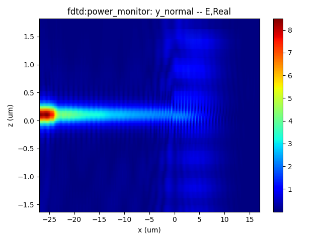
Electric profile
When the wavelength of the incident light meets the Bragg condition, the incident light will enter the waveguide through grating coupling.
 |
|---|
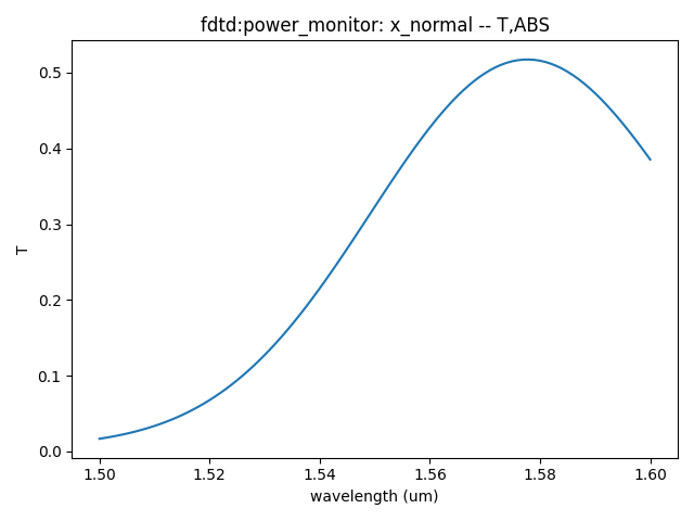
Transmission
The transmittance of grating coupling varies with wavelength as shown in the following figure.
 |
|---|
References
D. Taillaert, F. Van Laere, M. Ayre, W. Bogaerts, D. Van Thourhout, P. Bienstman and R. Baets, “Grating Couplers for Coupling between Optical Fibers and Nanophotonic Waveguides,” Japanese Journal of Applied Physics, vol. 45, no. 8a, pp. 6071-6077, 2006.